Young‘s Modulus Apparatus – Hall Sensor Bending Method
Product Overview
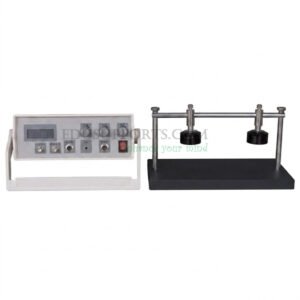
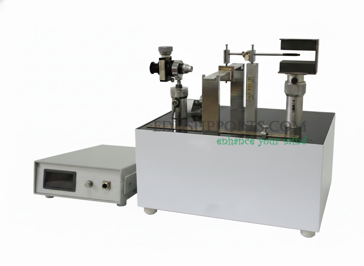
The Edusupports Young’s Modulus Apparatus (SKU: 0301040040) is a comprehensive, high‑precision laboratory instrument designed to teach the fundamental concept of Young’s modulus through the bending (flexural) method. Unlike traditional tensile testing setups, this apparatus uses a thin metal beam specimen supported at both ends, with a force applied at its center to induce measurable bending deformation. A Hall‑effect displacement sensor provides non‑contact, highly linear measurement of the resulting micro‑displacement, converting it into an output voltage that is directly proportional to the deflection.
This apparatus bridges the gap between classical mechanics and modern electronic measurement techniques. Students not only determine the Young’s modulus of brass and malleable cast‑iron samples but also learn how a Hall‑effect sensor can be calibrated and used as a precise micro‑displacement transducer. The complete system includes a reading microscope for direct visual verification, a digital voltmeter for sensor output, a full set of calibration weights, and a detailed experiment manual. It is an ideal teaching tool for university physics and engineering departments, as well as advanced high school programs.
Key Features
Bending Method Measurement – Determines Young‘s modulus by applying known weights to a simply supported beam, a technique widely used in materials science.
Hall‑Effect Displacement Sensing – Utilises a linear Hall sensor with a sensitivity of >250 mV/mm over a 0–2 mm range, providing contact‑free, high‑accuracy deflection measurement.
Dual Measurement Verification – Displacement can be measured both electronically (via Hall sensor) and optically (via reading microscope), allowing students to compare methods and understand sensor calibration.
Complete Sample Set – Includes both brass and malleable cast‑iron sheets, enabling comparative studies of different material stiffness.
High‑Quality Optical Components – Reading microscope with 20× magnification, 0.01 mm resolution, and 8 mm measurement range.
Digital Readout – 3½‑digit digital voltmeter with selectable ranges (0–200 mV and 0–2000 mV) for precise Hall sensor output monitoring.
Stable, User‑Friendly Design – Heavy‑duty cast base with adjustable levelling feet; pre‑aligned magnet assembly and sensor mount for quick setup.
Comprehensive Accessories – Supplied with 8×10 g weights, 2×20 g weights, connection cables, and a detailed experiment manual including sample data and error analysis.
Detailed Specifications
| Parameter | Details |
|---|---|
| SKU | 0301040040 |
| Measurement Method | Bending (flexural) of simply supported beam |
| Displacement Sensor | Hall‑effect linear sensor |
| Sensor Sensitivity | >250 mV/mm (typical) |
| Sensor Linear Range | 0 – 2 mm |
| Reading Microscope | Range: 8 mm; Resolution: 0.01 mm; Magnification: 20× |
| Digital Voltmeter | 3½‑digit LED display; Ranges: 0–200 mV / 0–2000 mV |
| Weights | 8 pieces × 10.0 g; 2 pieces × 20.0 g |
| Test Specimens | Brass sheet; Malleable cast‑iron sheet |
| Measurement Uncertainty | < 3% relative to reference values |
| Power Supply | 220 V AC / 50 Hz (or as specified for export) |
| Dimensions (approx.) | Base unit: 350 mm × 250 mm × 120 mm |
| Total Weight (approx.) | 5.0 kg |
Included Components
| Component | Quantity |
|---|---|
| Main electronic unit (digital voltmeter + Hall sensor signal conditioner) | 1 |
| Mechanical unit (base, support posts, knife‑edges, specimen holder) | 1 |
| Reading microscope with stand | 1 |
| Hall sensor assembly (pre‑mounted on adjustable lever) | 1 |
| Magnet pair with adjustable mount | 1 |
| Connection cable (3‑pin) | 1 |
| Weight set: 10 g (8 pieces) | 8 |
| Weight set: 20 g (2 pieces) | 2 |
| Brass specimen sheet | 1 |
| Malleable cast‑iron specimen sheet | 1 |
| Level bulb | 1 |
| Spare screws and hex keys | 1 set |
| Experiment manual (including theory, procedure, and sample data) | 1 |
Note: A set of three levelling screws is pre‑installed on the base. A rectangular copper frame with a baseline is also included for microscope alignment.
Core Experiments
This apparatus supports a progressive, three‑stage laboratory exercise:
Hall Sensor Characterisation and Calibration
Students learn the operating principle of a Hall‑effect sensor. By applying known displacements (measured by the reading microscope) and recording the corresponding output voltage, they generate a calibration curve and determine the sensor’s sensitivity (ΔV/ΔZ). The linear relationship between voltage and displacement (within the 0–2 mm range) is clearly demonstrated.Young‘s Modulus Measurement of Brass (Bending Method)
Using the calibrated Hall sensor (or the reading microscope as a reference), students apply increasing loads (from 10 g to 100 g in 10 g steps) to the brass beam. The central deflection ΔZ is recorded at each load. Young’s modulus is then calculated using the standard bending formula:Y = (d³ · M · g) / (4 · a³ · b · ΔZ)
where
d = support span
a = beam thickness
b = beam width
M = applied mass
g = gravitational acceleration (9.794 m/s²)
ΔZ = deflection
Comparative Measurement of Malleable Cast Iron
The same procedure is repeated with the malleable cast‑iron specimen. Students compare the Young’s modulus values of the two materials and discuss how microstructure (brass vs. cast iron) affects stiffness.Typical experimental results:
For brass sample: Y ≈ 10.6 × 10¹⁰ N/m²
For malleable cast iron sample: Y ≈ 18.5 × 10¹⁰ N/m²
These values are within 3% of accepted reference values.
Theory in Brief
Young’s Modulus (E) is a fundamental material property that quantifies stiffness: it is the ratio of tensile/compressive stress to strain within the elastic limit. For a beam of rectangular cross‑section supported at both ends and loaded at the centre (three‑point bending), the deflection at the midpoint is directly related to the applied force and the beam’s geometry. The bending method avoids the need to grip the sample, making it particularly suitable for thin, brittle, or irregularly shaped specimens.
Hall‑effect displacement sensing exploits the linear relationship between the output voltage of a Hall element and its position within a specially designed non‑uniform magnetic field. Two identical magnets are arranged with like poles facing each other, creating a region where the magnetic flux density changes linearly with position. When a constant current is passed through the Hall element, its output voltage is directly proportional to the displacement from the central null point. This principle allows the apparatus to measure micro‑displacements (down to 0.01 mm) with high repeatability and without mechanical contact.
Setup and Operation Summary
Levelling – Place the apparatus on a stable bench. Use the three adjustable feet and the supplied level bulb to level the base.
Specimen mounting – Insert the chosen sample (brass or cast‑iron sheet) into the copper frame and position it on the two knife‑edge supports.
Lever assembly – Mount the Hall sensor lever so that the sensor sits centrally between the two magnets and the lever‘s knife‑edge engages with the V‑groove on the specimen holder. Adjust magnet height if necessary.
Microscope alignment – Focus the reading microscope on the baseline mark of the copper frame. Zero the microscope’s vernier scale.
Electrical zeroing – With no load applied, adjust the “Zero” knob on the electronic unit until the digital voltmeter reads 0 mV (or a very small value). Preheat for 10 minutes for best stability.
Measurement – Add weights in 10 g increments up to 100 g. At each step, record both the microscope reading (ΔZ) and the Hall sensor output voltage (U). Remove weights in reverse order to check for hysteresis.
Calculation – Use the recorded data to calculate Young‘s modulus using the formula above. Plot U vs. ΔZ to verify sensor linearity and determine its sensitivity.
Why Choose the Edusupports Young’s Modulus Apparatus?
Modernises a classic experiment – Replaces unreliable optical levers or dial gauges with a robust, linear Hall sensor, giving students exposure to real‑world industrial sensing technology.
Dual measurement capability – The reading microscope provides a direct, visual check of the sensor‘s accuracy, reinforcing the concept of sensor calibration.
Excellent value – Competitively priced for educational budgets without compromising on build quality or experimental precision (<3% uncertainty).
All‑in‑one kit – Everything needed for a complete lab session is included: samples, weights, tools, and a full manual with sample data and error analysis.
Built to last – Heavy‑duty cast base, precision‑machined supports, and robust electronics ensure years of reliable service in a teaching environment.
Ideal for curriculum requirements – Covers key learning objectives: Hooke’s law, elastic deformation, stress‑strain relationships, sensor characterisation, and data analysis using least‑squares or graphical methods.
Ideal For
University physics and engineering laboratory courses
Materials science and mechanical engineering teaching labs
Advanced high school physics programs
Laboratory courses focusing on non‑electrical quantity measurement techniques
Research and development labs needing a reliable bending‑method test stand
Safety and Maintenance
Always handle the Hall sensor lever and reading microscope with care to avoid misalignment.
Do not exceed the recommended maximum load (100 g). Overloading may permanently deform the test specimens.
Keep the magnet faces clean and free of ferromagnetic debris.
After use, remove all weights from the hanger to prevent creep in the sample.
Store the apparatus in a dry, dust‑free environment. The reading microscope should be kept in its protective case when not in use.