
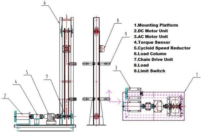
AC DC Motor Driving Control Trainer, featuring an AC motor, DC motor, frequency converter, coupling, torque and speed sensor, reducer, sprocket, chain, weights, and more, is designed for comprehensive control experiments of AC and DC motors, including mapping their characteristic curves. The control unit uses relay control and Siemens PLC. Ideal for universities, colleges, vocational schools, and technical schools, the trainer enables:
- 1.Understanding the structure and working principles of mechanical and electrical transmission control
- 2.Characteristic testing of AC and DC motors
- 3.Relay control experiments for AC and DC motors
- 4.Upper computer control experiments for AC and DC motors
- 5.PLC (Programmable Logic Controller) experiments
- 6.Mechanical transmission experiments

- 1.This system intuitively displays the entire process of driving control in a mechatronics system.
- 2.Dual control modes: The relay control mode helps students master traditional relay control principles and wiring, while the PLC control mode offers simpler wiring, significantly reducing preparation time for experiments.
- 3.The experiment software supports real-time tests, results saving, printing, and simulation. It can generate four types of characteristic curves (both real-time and historical): T-n curve, t-T curve, t-n curve, and t-V curve.
- 4.The optional PLC experimental part integrates a programmable logic controller, programming software, and analog signal/analog quantity components to complete basic PLC instruction experiments, switch signal/value experiments, analog signal/quantity experiments, and communication experiments.
The System Structure
- 1.Frequency converter unit;
- 2.DC unit: Contains DC speed regulator and DC contactor;
- 3.AC unit: Contains thermal relay and AC contactor;
- 4.Control unit: contains button, time relay, intermediate relay;
- 5.Resistance unit: 10Ω / 50W;
- 6.PLC unit: Contains PLC module, A/D module and intermediate relay;
- 7.Power supply unit: provide 380V, 220V
- A.AC motor experiments
- 1.Series rotor resistance start with time relay control
- 2.Variable voltage start
- 3.Jog/automatic control
- 4.Cycle work and return to start
- 5.Y-△ reduced-voltage start
- 6.Reverse connect brake
- 7.Series rotor resistance start with current control
- 8.Dynamic braking
- 9.Positive and negative turn control
- 10.Variable frequency control
- 11.Variable frequency brake
- B.DC Motor Experiments
- 1.Positive and negative turn
- 2.Series resistance start
- 3.Reduced-voltage start
- 4.Variable resistance control
- 5.Variable voltage control
- 6.Dynamic braking
- 7.Power reversal connection
- 8.Plugging braking
- C.Mechanical Transmission Experiments
- 1.Electromechanical driving system assembly (motor part)
- 2.Chain drive efficiency test
- 3.Calculation and testing of rotational inertia
- D.PLC Programmable Controller Experiments (Optional)
- 1.Digital quantity/digital value
- 2.Analog signal/analog quantity
- 3.PLC communication
The Main Technical Parameters
Specification | ||
SKU | ||
DC Motor | Power Supply | 220V |
Power | 0.75Kw | |
Torque | 4.72Nm | |
Speed | 1500r / min | |
AC Motor Reducer | Power Supply | 380V |
Power | 0.75Kw | |
Torque | 2.3Nm | |
Speed | 950r / min | |
Cycloid Speed Reductor | Reduction Ratio | 1: 9 |
Torque | 0-250N.m | |
Frequency Converter | Power Supply | 380V |
Power | 0.75Kw | |
Output frequency | 0.1 ~ 400Hz | |
Torque and Speed Sensor | Range | 0-20N.m |
Tachometer Output | 60 pulses/coil | |
Module | PLC | S7-200 series CPU224 |
A/D | Siemens EM235 | |
Torque Sensor | Range | 0-20Nm |
Load |
| 14kg/pcs |
Weight |
| 1kg, 4pcs |
Bench Dimensions | L × W × H | 1560 × 740 ×1700mm |
Transmission Dimensions | L × W × H | 1210 × 620 × 510mm |
The Height of Transmission Frame |
| 2000mm |


